


 All4Nutra

Dissertation by Ilias El Aita: Part 2
The term 3DP is an umbrella term encompassing several technologies, which differ in the printing style and/or used material. Nevertheless, these technologies have the same starting point in common as illustrated in Figure 1. All 3DP technologies share the same procedure of fabricating solid objects from a digital model. The procedure is divided into 5 subsections which are described in detail below.
1 Creation of a CAD model & conversion to a STL file
The 3DP process always starts with designing a digital model. CAD software is commonly used to create digital models in the first step. After designing the desired model with the CAD software, it is converted into a stereo lithography file format (STL file). The STL file contains information about the external surface of the model. This STL file serves as basis for the sequential processes in the printing process.
2 Transfer to slicing software
After the design phase, the STL file is imported within the next step into a slicing software. The slicing software converts the STL file into a G-code, numerical control (NC) programming language. Through the G-code, the action of the used 3D-printer can be controlled. Furthermore, changes of building parameters like supporting material, layer height or the orientation of the object are possible in this stage of process.
3 Transfer to the machine & machine setup
Once the G-code has been created, it will be provided to the respective 3D-printer. At this stage of process, relevant printing parameters can be set to control the process.
4 Printing phase & removal
At this stage, the desired object is printed layer-wise. The building step is completely automated and needs therefore no supervision by the operator. Most 3D-printers have a built-in control unit that controls the process and in the event of a deviation, aborts the process and displays an error message. As soon as the printing process is finished, the object can be removed from the building platform. Depending on the used printing technology safety aspects must be considered during removal of the finished object from the platform.
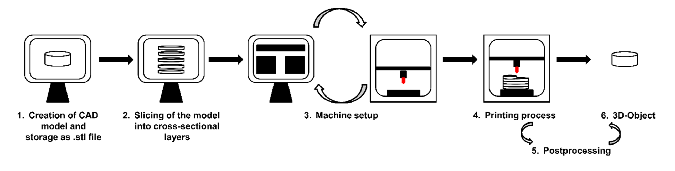
5 Post-processing
Depending on the used printing technology, post-processing procedures are essential to achieve a certain product quality. Some printing technologies require for example a post-thermal treatment to increase the mechanical strength. The relevant printing technologies covered by the term 3DP are indicated in Figure 2.
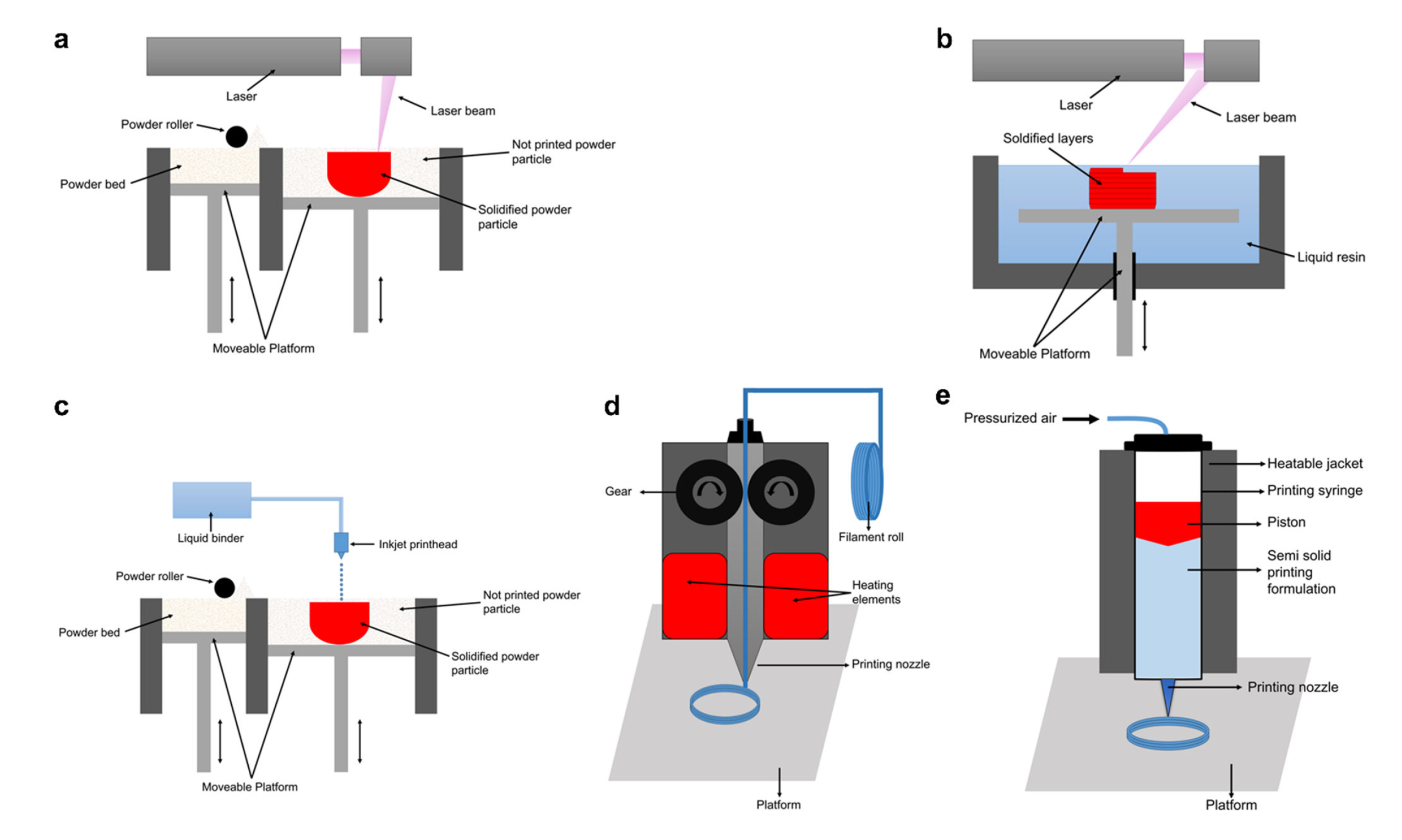
The printing technology powder bed fusion (PBF) comprises three different printing techniques: selective laser sintering (SLS), direct metal laser sintering (DMLS) and selective laser melting (SLM). These printing technologies share the same working principle and differ from each other in the used printing material and therefore the required energy input (Figure 2a).
DMLS and SLM are predominantly used in the aerospace and automotive industry [36, 37]. SLS printing gained recently increasing interest as manufacturing process for pharmaceutical products [38-43] as well as for the production of bone scaffolds [44-46] and implants [47]. During the printing process, a polymer powder layer of the starting material is spread onto a building platform using a roller. The spread polymer powder layer is then preheated inside the printer to temperatures just below the respective melting point of the polymer [48, 49]. Subsequently, a laser scans the surface of the polymer powder layer, sintering selective parts of a cross section of the object to be printed. The absorbed laser heat energy causes a melting of the powder particles, which leads to a fusion of neighbored particles [50]. After scanning the entire cross section, the building platform is lowered by the thickness of one layer and a further powder layer is spread over the previous layer using the roller. The sintering process is repeated until the complete object is formed. After finishing the printing process non-sintered powder must be removed [51].
SLS has been studied recently as manufacturing process for oral solid dosage forms [41-43]. Depending on the used polymer, different dissolution profiles were achieved. Further, adjustment of laser scanning speed affected the resulting disintegration of printed tablets [42]. SLS has been further utilized to manufacture orodispersible printlets containing ondansetron [52]. A recently published study introduced the ability of producing dosage forms with unique surface pattern which allows visually impaired patients to differentiate their medication [53]. During the printing process, the used powder bed acts as support material for the printed object, so no further additional supporting material is needed. Nevertheless, the accumulation of non-sintered powder material represents a major drawback of the technology. For pharmaceutical applications, a verification must be performed, whether the non-sintered powder must be classified as drug containing waste or might be recycled. Since highperformance lasers are applied during the PBF printing process, degradation of API as well as of excipients might occur, which would represent a further problem for any re-use [43].
The stereo lithography (SLA) printing is based on the selective photo-polymerization of a liquid resin via an ultraviolet (UV) laser beam (Figure 2b) [54]. In comparison to the other 3DP technologies the resulting resolution of printed products is clearly superior. The use of other printing technologies provides objects with a resolution of 50 – 200 μm, whereas with SLA printing a resolution of up to 20 μm can be achieved [55]. The printing process starts with filling the liquid into a basin, which has an integrated movable building platform [56]. The platform is then adjusted to the height of a single layer to the surface. In the next process step, the UV laser beam traces a cross-section of the object to be printed on the surface of the liquid resin.
Through the exposure of the liquid resin to the UV laser beam, the monomer carbon chains of the resin are activated forming a coherent layer through solidification. After the first layer is manufactured, the building platform moves down automatically by the thickness of a single layer. The scanning and solidification processes then start again from the beginning and are repeated until the complete object is manufactured [54]. Post processing is necessary either to remove excessive resin with solvents like isopropanol or to increase the mechanical properties of the printed object by UV light exposure [55].
The application of SLA technology is still in the initial development stage and needs to overcome some major hurdles and challenges to be recognized as suitable manufacturing process for pharmaceutical use. Especially the hazardous properties of the used resins cause SLA not being applied in manufacturing of pharmaceutical dosage forms currently [34]. During the printing process, residual monomers and photo-initiator molecules might be entrapped into the structure of the photo-polymerized structure. These can be cytotoxic upon leaching out of the structure and lead to undesirable effects when the printed structure is used for humans. Furthermore, the used resins are photosensitive, which also might lead to stability issues during storage of produced dosage forms. The occurrence of chemical reaction between a photopolymer and an API has to be taken into consideration during the selection process, since a chemical reaction might affect the product quality negatively [57]. Nevertheless, there are some scientific studies available adapting SLA printing for the manufacturing of pharmaceutical dosage forms [58-60]. Further, SLA has been used recently to print a bladder device containing lidocaine enabling an intravesical drug delivery [61].
Depending on the printed shape (hollow or solid), a sustained drug release up to 14 days was achieved [61]. With regard to commercial sales in pharmaceutics, binder jetting (BJ) is currently the most successfully applied 3DP technology (Figure 2c). Until now, it is the only 3DP technology that resulted in a commercialized product [62]. The drug approval of the 3D-printed product Spritam® (Aprecia® Pharmaceuticals) by the FDA represents a significant milestone in the development and establishment of 3DP processes as manufacturing processes for solid dosage forms. Commercialization of a printed product increase the interest of manufactures in printing technologies as manufacturing process and thus financial resources could be generated for research and development of 3D-printers as well as for printable materials.
The printing process of BJ starts with spreading a thin powder layer onto the building platform using a recoating blade [63]. Subsequently, an inkjet printer head is moved over the powder bed depositing droplets of a binder solution onto the powder bed. The movement of the print head is controlled via the G-code. Through the printed solution the powder particles are wetted causing a local hardening and therefore layer solidification. After the first layer solidifies, the building platform is lowered by the thickness of a single layer and a new powder layer is spread over the previous solidified layer. The printer head is moved to the initial position and the deposition process of droplets onto the powder layer is repeated. The printing steps are repeated until the desired object is printed completely. After finishing the printing process, the printed object needs to be removed from the powder bed and loose powder discarded carefully [63, 64]. Execution of post processing like thermal sintering is often necessary to improve the mechanical properties of printed objects [63]. In pharmaceutical application, BJ process can be carried out in two different variants. The API can be present in the powder mixture as well as dissolved in the binder solution. For both variants, the printing process is the same as described above. For pharmaceutical application, feasibility of implementing BJ as manufacturing process for oral solid dosage forms has been demonstrated in various scientific studies [65-71]. These studies revealed the opportunity of manipulating the drug release by either using polymers with different characteristic like basic butylated methacrylate copolymer (Ph. Eur.) (Eudragit® E 100) and ammonio methacrylate copolymer type A (Ph. Eur.) (Eudragit® RL PO) as binder material or by designing complex geometries.
Due to the low thermal stress during the printing process, BJ printing enables the processing of thermo-sensitive APIs. Additionally, colored additives can be added to the printing inks, improving the patient´s compliance. Objects printed with BJ printing display a fragile structure with high friability and inferior mechanical properties, which make them rather unsuitable for further handling and packaging processes [34]. Further, post-processing step is required to remove residual powder after the printing process which increase the manufacturing time.
A further 3DP technology of interest is the fused filament fabrication (FFF) printing technology, in the printing community also called fused deposition modeling (FDMTM) (Figure 2d) [72]. In most areas of scientific research and development, FFF is the widely used printing technology. Thereby, the number of scientific research articles using FFF as manufacturing process for pharmaceutical dosage forms increased significantly in the last years compared to the other printing technologies. Reasons for this might be that after the expiration of the original patent in 2009 [72], the number of available FFF printers has risen tremendously, causing a significant drop in the acquisition costs of FFF printers. FFF printing technology requires the premanufacturing of filaments using for example hot melt extrusion (HME) [73, 74] or incubation of commercially available filaments like polyvinyl alcohol (PVA) or polylactic acid (PLA) filaments in drug-loaded solutions [75-78]. Since the achievable drug load via incubation is low, the incubation in drug-loaded solutions is not of interest for pharmaceutical purposes. During the printing process the premanufactured filament is loaded into the printer using a gear system [75]. The applied filament is mechanically stressed by the gear system, which therefore must provide a certain mechanical resilience to ensure printability [73]. During the FFF printing, the printing nozzle is heated causing the filament to melt within the nozzle. The molten filament is then extruded through the heated tip of the nozzle onto a building platform, where solidification of printed material takes place. The movement of the print head is repeated layerwise until the object is printed completely. The approach of FFF printing as manufacturing process has been carried out to manufacture for example patient-tailored tablets [30, 78, 79], tablets with combined different drug release mechanisms [79, 80] or to print network structures with predictable drug release kinetic [81]. Especially, modulating the resulting drug release behavior of printed drug delivery systems has been explored utilizing FFF printing either achieving an immediate drug release [82] or a sustained drug release [83-85]. Furthermore, general requirements to ensure printability has been investigated intensively [73, 86-89]. The exploration of FFF printing technology is already advanced compared to the other 3DP technologies.
Objects printed by FFF technology do not necessarily need a post-process treatment, by which the overall manufacturing time might be reduced compared to other printing technologies like BJ or SLA. FFF printing provides objects with sufficient mechanical properties, which do not need further post treatment, and which allow packaging by the manufacturer as well as safe handling by the patients. Besides the mentioned advantages, there are some disadvantages to consider regarding the use as pharmaceutical manufacturing process. Especially the thermal stress during the filament preparation via HME as well as during the printing process might limit the number of processable APIs due to possible thermal degradation of the ingredients (API and excipients) [76, 90]. Insufficient temperature adjustment of the printing nozzle might lead to nozzle clogging caused by solidification of the polymer within the printing nozzle.
For the present thesis, pressure-assisted microsyringe (PAM) printing technology was selected as preferred manufacturing process (Figure 2e). PAM printing technology was invented in 2002 by Vozzi and colleagues as an alternative manufacturing process in the field of tissue engineering and bioprinting [91]. In the first version of the invention, the printer was equipped with a glass syringe, an electronic pressure controller and a computer as a control unit for the process parameters [91, 92]. Over the last years, the invention has been further elucidated resulting in a fully automated and controllable printing process [93, 94].
The PAM printing technology requires semi-solid formulations as printing material. Semi-solid formulations are achieved usually by gelling of polymers [95-97] or by dissolving gel-formers into either water or organic solvents [98]. In the first stage of the process, the prepared printing formulation is transferred into a printing syringe and closed with a piston or plunger at the top. The printing process is carried out by applying pressurized air to initiate the extrusion of the semi-solid formulation from the syringe through the adapted printing nozzle [91-94]. The printing pressure must be sufficient enough to enable a constant flow of the material out of the printing nozzle. Usually printing pressures ranging from 3 – 5 bar are used during the PAM printing process [95-99].
To ensure a successful process, the selected material should provide the ability to form a stable object without collapsing during the printing process. Since the printing formulations are based on solvents (organic and inorganic), a drying step is essential to achieve a solid 3D-object [95, 100]. Due to the necessary drying process shrinkage of the printed object is expected [34].
The choice of the nozzle diameter mainly depends on the rheologic properties of the used printing material. Materials with high viscosities are not processable with a small nozzle diameter due to the occurrence of nozzle clogging. Since the solidification of the printed material does not occur directly after being extruded onto the building platform, the printing temperature and building platform temperature are of great importance for the PAM technology. The printing process is determined by the dynamic viscosity of the material, which is also determined by the temperature as well as by the applied shear stress. A high printing temperature would decrease the viscosity of the printing material, which would lose its semisolid nature and become too liquid for the execution of the printing process. Printing of these formulations would lead to the complete spreading of the formulation on the building platform without the ability of forming a stable structure. On the other side, a low printing temperature would result in a high viscosity which might not be suitable anymore for the PAM printing process, since the printing pressure would not ensure a constant flow of material through the printing nozzle. The applied printing pressure mainly depends on the viscosity of the printing material. Materials with a high viscosity require high printing pressure to enable a constant material flow, while low viscosity materials require rather low printing pressure to achieve a suitable extrusion through the applied nozzle. Additionally, the viscosity of the printing material determines the applicable printing speed. During the printing process, a constant material flow should be realized to avoid printing errors, which might result in dose variations for pharmaceutical application. For printing materials with a high viscosity, a high printing speed would result in an irregular extrusion of the material, which would result in significant fluctuations in the dose. For materials with a low viscosity, a lower applied printing speed might result in regional over extrusion, which would result in an overdosing of API.
Although until today this technology is mainly used in the field of tissue engineering and bioprinting, it has great potential to be implemented as manufacturing process for individualized dosage forms with unique dissolution characteristics [101-104] as well as for the manufacturing of fixed dose combinations [95, 96, 105]. Shaban et al. utilized PAM printing to manufacture a fixed-dose combination product named polypill [97]. The printed polypill consisted of five different APIs with different release profiles [97]. Acetylsalicylic acid and hydrochlorothiazide were printed into one immediate release (IR) compartment, while atenolol, pravastatin and ramipril were embedded in a sustained release (SR) compartment. The IR compartment was printed on top of the SR compartment and consisted of sodium starch glycolate as disintegrants and polyvinylpyrrolidone (PVP) K30 as binder (Figure 3).
![Figure 3. Scheme of the polypill concept (adapted and modified from [97], used with courtesy of the International Journal of Pharmaceutics, Elsevier)](https://www.pharmaexcipients.com/wp-content/uploads/2021/05/Figure-3.-Scheme-of-the-polypill-concept-adapted-and-modified-from-97-used-with-courtesy-of-the-International-Journal-of-Pharmaceutics-Elsevier.png)
PAM printing technology enables the execution of the printing process at room temperature. Hence, PAM is a promising technology for the processing of thermo-sensitive API even at ambient conditions. In addition, printing of pharmaceutical pastes with this technology appears to be feasible, which enables a high drug-load for pharmaceutical application [99]. Beside manufacturing of tablets, PAM printing was utilized to print ODFs [105]. ODFs were printed directly into their final size by which a further cutting step is not required anymore [105].
For the execution of printing processes, plastic syringes as well as plastic nozzles are used. Besides the plunger to close the syringe at the top, these parts are the only ones that are in direct contact to the printing formulation. Since the acquisition cost of these components are negligible, they might be used as disposable item to avoid cross-contamination. Therefore, complex cleaning concepts for PAM printing are redundant, compared to other 3DP technologies like FFF printing where the starting material is in direct contact to the equipment. The use of disposable printing components makes it further possible to switch easily to other APIs, since there is no necessity to remove not printed powder material between the printing processes as it is the case for printing technologies like BJ or SLA.
Besides the advantages, the use of PAM technology as pharmaceutical manufacturing process shows some limitations. Especially, the use of organic solvents in the preparation of the printing formulations like acetone or DMSO must be considered as critical. According to the ICH guideline for residual solvents, acetone and DMSO are listed as a class 3 solvents, meaning that the daily intake for humans is limited to 50 mg [106]. Especially dosage forms intended for paediatric use should not contain the mentioned solvents to avoid possible harm of paediatric patients. Thus, for printing formulations containing organic solvents, a determination of the residual solvent according to the Ph. Eur. is required [107]. Furthermore, the usually required drying process should also be considered as a critical step in the manufacturing cascade. Drying processes are often long-term processes utilizing often high drying temperatures [34]. Due to the thermal stress, the stability of APIs and excipients might be influenced because of their possible thermal degradation. Nevertheless, the overall thermal stress is lower compared to printing technologies like FFF printing. Another issue to consider is that the achievable resolution is limited by the applied nozzle size. For pharmaceutical applications, nozzles of 400 – 800 μm diameter are available, which is clearly inferior compared to other printing technologies [34, 95, 96, 99, 100].
Download the full dissertation about 3D printing here!
See Part 1: “Introduction to 3D-printing” here and Part 3: “Advantages and challenges of pharmaceutical 3D printing” here!
Article information: Ilias El Aita. Inaugural-Dissertation: Manufacturing of solid dosage forms using pressure-assisted microsyringe 3D-printing, 2021. Heinrich-Heine-University Düsseldorf.
See the references in the PDF document!
Find our full pharmaceutical 3D printing overview article here
OR
Visit our 3D printing special here


